Description
  |
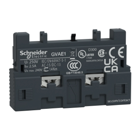
For thermal-magnetic motor circuit-breakers GV2ME, GV2P and GV3P Contact blocks |
|||||
| Description | Mounting | Max. nos. |
Type of contacts |
Sold in lot of |
Unit Reference |
|
| Instantaneous | Front (1) | |||||
| auxiliary contacts | Side (LH) |
2 | N/O + N/C N/O + N/O N/O + N/C N/O + N/O |
10 10 1 1 |
GVAE11 GVAE20 GVAN11 GVAN20 |
|
| Fault signalling contact + instantaneous |
Side (3) (LH) |
1 | N/O (fault) + N/O + N/C |
1 1 |
GVAD1010 GVAD1001 |
|
| auxiliary contact | N/C (fault) + N/O + N/C |
1 1 |
GVAD0110 GVAD0101 |
|||
| Short-circuit signalling contact |
Side (LH) |
1 | C/O common point | 1 | GVAM11 | |
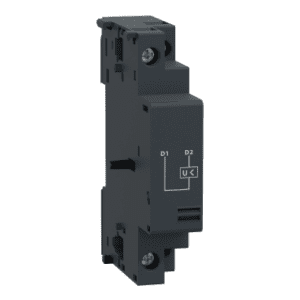  |
Electric trips – undervoltage or shunt trips (4) | |||
| Mounting | Voltage | Reference | ||
| Side of circuit-breaker |
24V 48V 110…115V 120…127V 220…240V 380…400V 415…440V |
50 Hz 50 Hz 50 Hz 50 Hz 50 Hz 50 Hz 50 Hz |
GVA•025 GVA•055 GVA•115 GVA•125 GVA•225 GVA•385 GVA•415 |
|
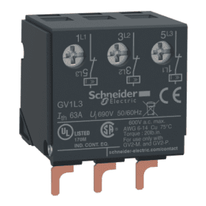  |
Electric trips – undervoltage or shunt trips (4) | ||
| Description | Mounting | Reference | |
| Limiters | At top (GV2 ME and GV2 P) |
GV1L3 | |
(1) Mounting of a GV AE contact block or a GV2 AK00 visible isolation block on GV2 P and GV2 L
(2) Choice of N/C or N/O contact operation, depending on how the reversible block is mounted.
(3) The GV AD is always mounted next to the circuit-breaker.
(4) To order an undervoltage trip: replace the dot ( ) in the reference with a U, example: GV AU025.
To order a shunt trip: replace the dot ( ) in the reference with an S, example: GV AS025.


