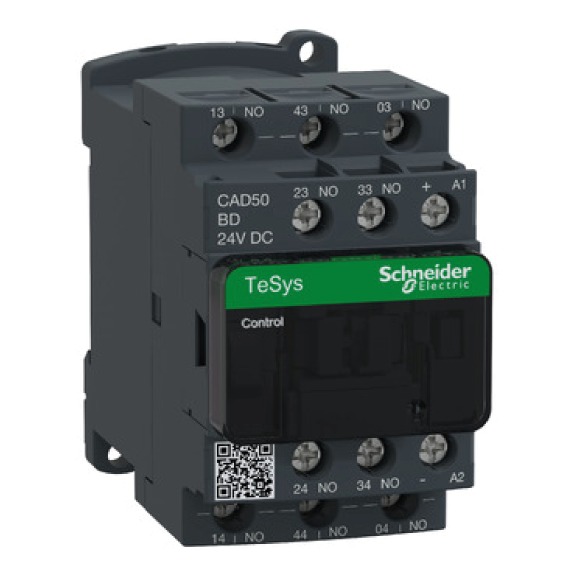
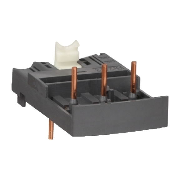
Description
| 0.06 to 110 kW at 400/415V: type 2 coordination | ||||||
| Type 2 Coordination According to IEC 60439-4-1, type 2 coordination requires that in the event of a short circuit, – contactor or starter must not present any danger to personnel or installation – must subsequently be able to resume operation |
||||||
| Number of contacts | Composition | Basic reference Complete with code indicating control circuit voltage (1) |
||||
| NO | NC | |||||
| 0.06 to 110 kW at 400/415V: type 2 coordination | ||||||
| 5 | 5 3 |
– 2 |
CAD50•• CAD32•• |
|||
| Instantaneous auxiliary contact blocks for connection by screw clamp terminals | ||||||
| Number | Maximum number per device | Composition | Reference | |||
| front | side | NO | NC | |||
| For use in normal operation environments | ||||||
| 2 | 1 – 1 – 1 – |
– 1 on LH side – 1 on LH side – 1 on LH side |
1 1 2 2 – – |
1 1 – – 2 2 |
LADN11 LAD8N11 LADN20 LAD8N20 LADN02 LAD8N0 |
|
| 4 (2) | 1 | – | 2 1 4 – 3 |
2 3 – 4 1 |
LADN22 LADN13 LADN40 LADN04 LADN31 |
|
| 4 (2) | 1 | – | 2 | 2 | LADC22 | |
Including 1 N/O and 1 N/C make before break.
| Time delay auxiliary contact blocks for connection by screw clamp terminals | ||
| Max. number per device |
Unlatching control |
Basic reference to complete for control voltage (4) |
| Front | Manual or electric | LA6DK10• |
| Coil suppressor modules (for mounting on CAD control relay) | ||
| Type | Operational voltage | Reference |
| RC circuits | 24…48Vac 110…240Vac |
LAD4RCE LAD4RCU |
| Varistors | 24…48Vac 50…127Vac 110…250Vac |
LAD4VE LAD4VG LAD4VU |
| Bidirectional peak limiting diode |
24Vac 72Vac |
LAD4TB LAD4TS |
| a.c. | |||||
| Volts ~ | 24 | 110 | 220 | 230 | 240 |
| 50/60 Hz | B7 | F7 | M7 | P7 | U7 |
| d.c. (coils with built-in suppression as standard) | ||
| Volts | 24 | 110 |
| U 0.7…1.25 Uc | BD | FD |
| Low consumption (coils with built-in suppression as standard) | ||
| Volts | 24 | 110 |
| U 0.7…1.25 Uc | BD | FD |
| Low consumption (coils with built-in suppression as standard) | |
| Volts | 24 |
| Code | BL |
(2) Blocks with 4 auxiliary contacts cannot be used on low consumption control relays.
(3) Power should not be simultaneously applied or maintained to the mechanical latching block and the CADN.The duration of the control
signal to the mechanical latching block and the CAD should be 100ms.
(4) Standard control circuit voltages
| Volts 50/60 Hz | 24 | 110/127 | 220/240 | 256/277 | 380/415 |
| Code | B | F | M | U | Q |


