Description
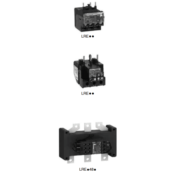
| Differential thermal overload relays for use with fuses or magnetic circuit-breakers GV2 L and GV3 L |
||||
| ■ Compensated relays with manual or automatic reset, ■ with relay trip indicator, ■ for a.c. |
||||
| Relay setting range (A) |
Fuses to be used with selected relay |
Type Rating |
Reference | |
| aM (A) | gG (A) | |||
| Class 10 A (1) for connection by screw clamp terminals | ||||
| 0.10…0.16 0.16…0.25 0.25…0.40 0.40…0.63 0.63…1 1…1.6 1.6…2.5 2.5…4 4…6 5.5…8 7…10 9…13 12…18 16…24 23…32 30…38 17…25 23…32 30…40 37…50 48…65 55…70 63…80 80…104 |
LC10.25 0.5 1 1 2 2 4 6 8 12 12 16 20 25 40 40 25 40 40 63 63 80 80 80 |
2 2 2 2 4 4 6 10 16 20 20 25 35 50 63 80 50 63 100 100 100 125 125 160 |
E06…E38 E06…E38 E06…E38 E06…E38 E06…E38 E06…E38 E06…E38 E06…E38 E06…E38 E09…E38 E09…E38 E12…E38 E18…E38 E25…E38 E25…E38 E38 E40…E95 E40…E95 E40…E95 E50…E95 E65…E95 E80…E95 E80…E95 E95 |
LRE01 LRE02 LRE03 LRE04 LRE05 LRE06 LRE07 LRE08 LRE10 LRE12 LRE14 LRE16 LRE21 LRE22 LRE32 LRE35 LRE322 LRE353 LRE355 LRE357 LRE359 LRE361 LRE363 LRE365 |
| Class 10 A (1) directly connected by connector | ||||
| 51…81 62…99 84…135 124…198 146…234 174…279 208…333 259…414 321…513 394…630 |
100 125 160 200 250 315 400 400 500 630 |
125 160 200 250 315 315 400 500 800 1000 |
E120…E160 E120…E160 E120…E160 E200 E200…E300 E250…E300 E250…E400 E300…E400 E500 E630 |
LRE480 LRE481 LRE482 LRE483 LRE484 LRE485 LRE486 LRE487 LRE488 LRE489 |
(1) Standard IEC 60947-4-1 specifies a tripping time for 7.2 times the setting current Ir:
Class 10A: between 2 and 10 seconds
(2) Direct mounting under contactor. For independent mounting of thermal overload relay
Order LAEB1 terminal block for LRE01…E35
Order LAEB3 terminal block for LRE322…E365


